What are ground loops, and why do they produce noise?
Notes on what I've learned about ground loops and generic grounding.

I write this blog post just to persist somewhere what I have learned about this topic. If you have feedback to improve this article, please let me know in the comments.
Ground loops
If you are familiar with audio equipment, I am sure you fear the following sound in your speakers or in your recording:
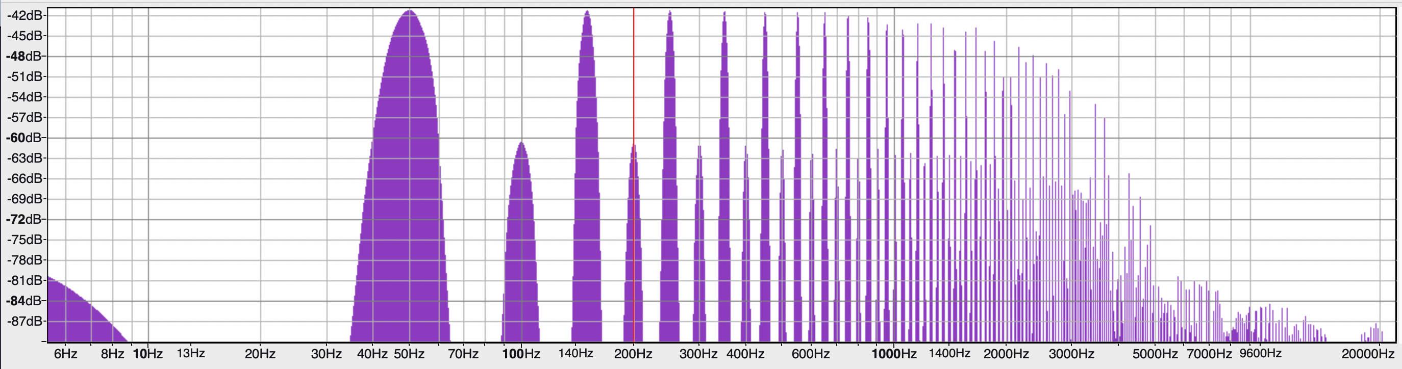
It feels like an interference of the mains AC 50/60Hz signal, with harmonics and other kinds of electric noises, that somehow got into your audio equipment. Typically, this sound is produced by a phenomenon that can appear with different terms: ground loop, common-impedance coupling, resistive crosstalk, return path coupling…
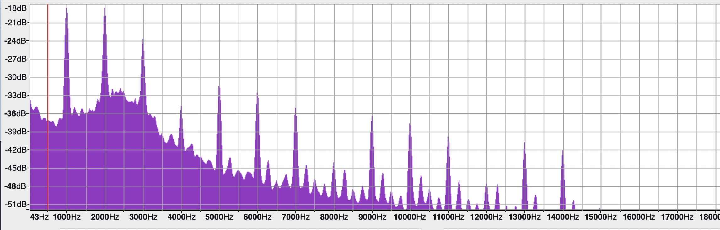
In other situations involving digital systems, ground loops can introduce digital noises of different nature. For example, USB connections involve digital signals with a frame rate of 1KHz, and ground loops can produce sounds like these ones:
This phenomenon can happen in long conductors connecting different audio systems in a PA or studio installation, or in the conductors within a single chassis. I use here these two terms:
Inter-system ground loops: the term “ground loop” typically refers to this situation.
Intra-system ground loops: in this situation, the preferred term is “common-impedance coupling”, but it actually refers to the same exact physical phenomena.
Inter-system and intra-system ground loops
Inter-system ground loops
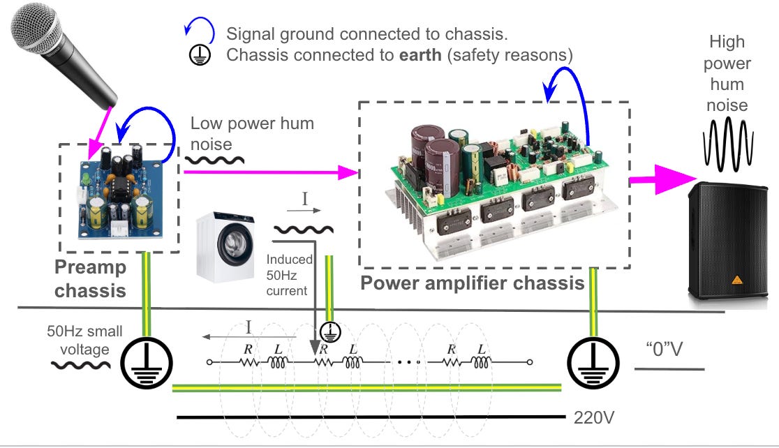
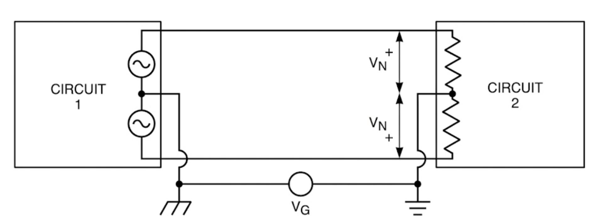
In audio engineering literature, a “ground loop” typically refers to two separate devices plugged into distant mains sockets but sharing an unbalanced audio signal. For safety reasons, each device’s local ground is usually connected to the building’s earth. However, because the physical earth connections at these distant sockets often sit at slightly different electrical potentials, the devices’ common grounds are forced to reference different voltages. This voltage difference fluctuates at 50/60Hz (the frequency of the AC mains), driving an unwanted current through the connecting cable’s shield and creating a noise voltage. When noise currents enter the ground, Ohm’s Law dictates that a voltage drop will occur, which the audio receiver misinterprets as part of the signal because of the unbalanced setting.
The following figure illustrates in a summarized way this issue:
For deeper understanding I have prepared an animated schematic in Falstad that illustrate the previous example shown in the figure. You can play the Falstad simulation here. The injection of current from the washing machine is happening through the capacitors of the EMI filter, and both audio devices are connected in an unbalanced way.
Note that the oscilloscope displays the voltage drop in the 100K input impedance of the Audio receiver: In unbalanced connections, the payload signal is the difference between the signal node and the ground node. As a consequence, variations of voltage in GND are misinterpreted as variations of voltage in the payload signal. Note how a loop must be closed between the earth connector and the audio cable’s shield in order for the current to flow, and how the impedance of the cables is causing a voltage drop due to the flowing current according to Ohm’s law. In essence, the interconnect shield and the external earth path form a resistive voltage divider. The amount of noise voltage that appears at the receiver depends entirely on the ratio between the main path’s impedance (the audio cable) and the external path’s impedance (the ground loop).
Inter-system ground-loop in the case of an USB device
When digital devices are involved (particularly those connected via USB Full-Speed (12 Mbps), ground loops often manifest as high-frequency digital interference rather than the traditional 50/60Hz mains hum. This occurs because the power consumption of digital systems fluctuates continuously alongside CPU activity and periodic clock rates, leading to unstable current in the ground return path. Because conductors possess non-zero impedance, these fluctuating return currents create a voltage drop between different points on the ground plane. The receiving equipment then misinterprets this voltage difference as part of the intended signal. While the underlying mechanism is identical to a standard AC ground loop (requiring a closed circuit that is often completed through the protective earth PE) the source of the interference differs entirely. Unlike standard mains hum, which relies on external AC devices inducing noise into the ground, digital ground loop noise is self-generated by the irregular return currents of the digital devices themselves.
Intra-system ground loops
When a similar voltage drop occurs inside a single device (where different internal circuits share a return path) experts sometimes use the terms common-impedance coupling or resistive crosstalk. The physics are similar, but the scale is localized to a circuit board. Despite these formal distinctions, you will frequently encounter the term “ground loop” used in a much broader sense. In everyday practice, it serves as a convenient, generic catch-all phrase covering both inter-system and intra-system grounding noise.
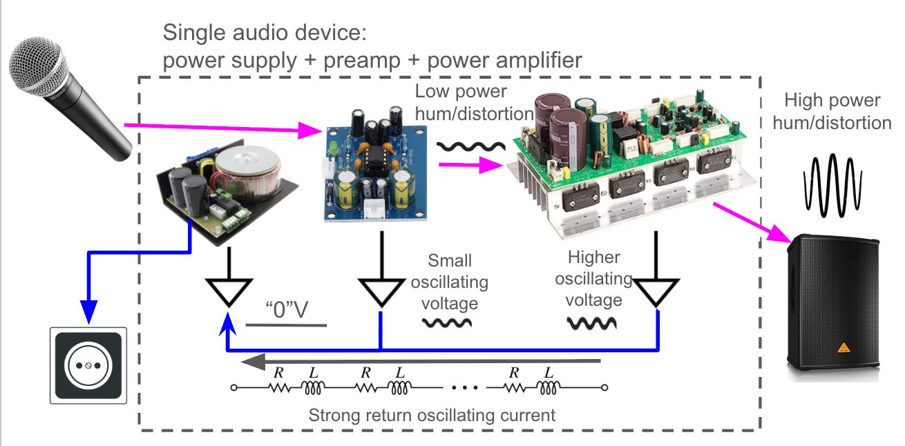
Similarly, we have prepared a Falstad simulation where we can observe how the impedance of the tracks connecting different GNDs can produce that the various GND voltages are not 0v, introducing noise, hum and distortion into the system.
Forget the word “ground”
As Bogatin and Kyttäla explain, the word “ground” is used for too many things, leading to confusion and misunderstandings, so we should forget about such word. We should rather differentiate the following concepts:
Earth ground: The physical connection driven literally into the dirt/floor of a building. It serves as the baseline reference for an entire building’s electrical system (like the third prong on a wall outlet). Its primary purpose is safety, ensuring that if a fault occurs, the high voltage has a safe path to the earth rather than through a person.
Chassis ground: The metal enclosure or housing of the device (e.g., the metal box of an audio mixer). When you plug a device into the wall, the chassis ground is typically tied directly to the earth ground for safety. Bogatin emphasizes that you should never use the chassis as an intentional return path for signals. If current accidentally flows through the chassis, different parts of the metal box will sit at different voltages, injecting noise into your audio signals.
Signal ground / Common node: A dedicated path used strictly to compare voltages. A true reference conductor must have negligible current flowing through it so that it suffers no significant voltage drop, ensuring the voltage at one end is perfectly identical to the other. Different type of signals in an audio device might have different local grounds: small signal, power signal, digital signals.
Return path (Return conductor): The physical route that current takes to get back to its source. If current flows through a conductor, it creates a voltage drop due to resistance or inductance.
Reference 0V ground: The node drawn in a schematic used as the 0 volts reference point. The schematic assumes this voltage is identical everywhere, but in reality, it is not. As a standard convention, this 0V schematic ground typically refers to the negative terminal of a battery or power supply in single-supply circuits, and to the center tap between the positive and negative voltage rails in dual-supply circuits.
Some of these concepts have a specific standard symbol:
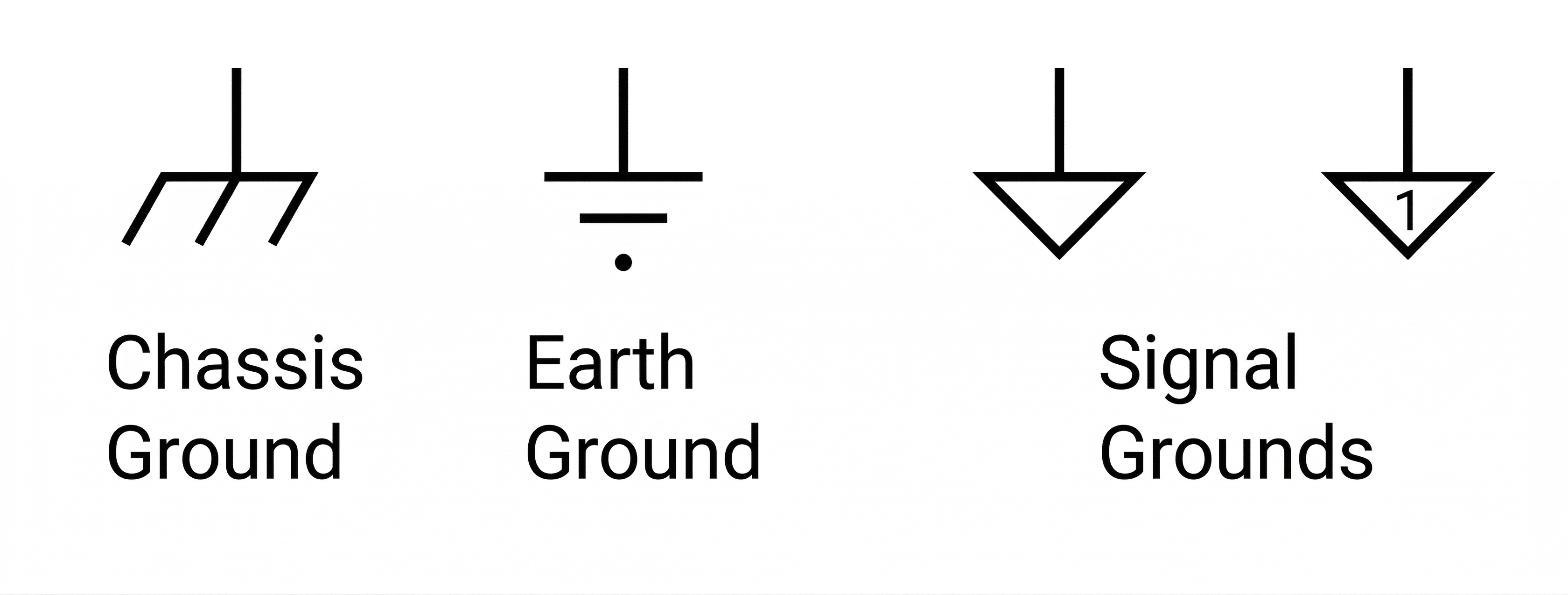
In audio equipment, the signal ground is typically set to the voltage of the earth ground for safety reasons, and this is the root of many problems. If you don’t do this, your signal ground can be floating on a potentially high voltage, which can produce a current through a human body when touching e.g. a connector with the feet in the actual earth ground.
Why do the “grounds” get noisy?
As we mentioned before, when noise currents flow through the ground, Ohm's Law dictates that a voltage drop will occur, which the audio receiver misinterprets as part of the signal. But… why noise currents flow through the ground?
There are three mechanisms in which noise currents enters the ground, or in which the loop is finally closed: conductive, capacitive and inductive. Each mechanism can appear intentionally or parasitically:
Conductive coupling: This happens when two different circuits share the exact same physical piece of copper. For example, in the case of a power amplifier: a heavy speaker draws massive, dynamically changing currents. If that 10-amp current flows back to the power supply through a shared ground trace, it multiplies against the copper's resistance. Even a fraction of an ohm creates a fluctuating voltage drop. Conductive coupling can also happen parasitically in several ways, either because of parasitic resistance, or because of parasitic conductivity. For example, there can be parasitic conductive coupling in cases where the insulation between two metallic parts is somehow damaged. In other situations, there can be parasitic resistance in situations where connectors, screws, etc. are not properly tightened, leading to unexpected voltage drops in conductors.
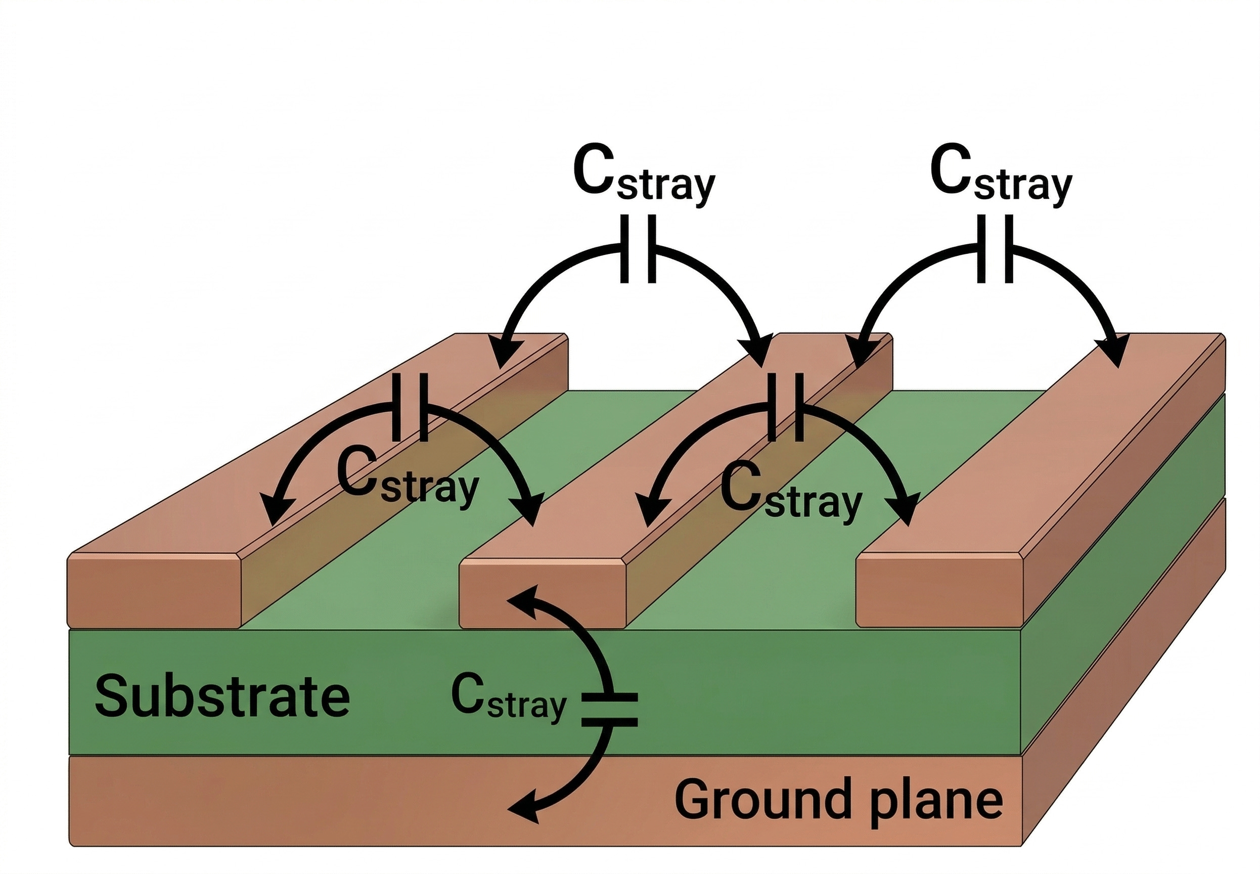
Capacitive coupling: Capacitors block DC but pass AC. Capacitive coupling occurs when changing voltages (AC mains, digital switching) push current into the ground path through an insulating barrier. Sometimes, the capacitance is intentional, like in the Y-capacitors of EMI filters, that can inject noise currents in the ground. In other situations, the capacitance can be parasitic: e.g. two parallel PCBs tracks or cables can produce a capacitive coupling between them (e.g. 220v mains and earth cables), or for example: a human body capacitively coupled with mains can then inject a 50Hz signal into the input through conduction. The parasitic capacitance, on the other hand, can help to close a ground loop, so even in double-insulated devices the loop can be closed under some circumstances.
Inductive coupling: If a ground wire forms a physical loop, an alternating magnetic field passing through it will induce a circulating alternating current directly into the wire. Given the same magnetic field, the larger the geometric area of this loop, the higher the induced voltage and resulting current. Actually, a wire loop behaves in two different ways: (1) near-field induction like in the secondary of a parasitic transformer, powerful in strong fields even at 50Hz (2) far-field radiation reception, which is very weak at 50Hz, but it is efficient at very high RF frequencies. This is the reason why the cables connecting audio devices should be twisted: to minimize the loop area, and therefore minimize induced currents. This is also why unbundled left and right RCA interconnects can cause hum even in entirely battery-powered systems; the physical space between the L and R cables creates a loop area that acts as the secondary of a transformer or an antenna. Always run your L and R cables tightly together. Additionally, keep high-current internal wires physically distant from signal wires to prevent near-field induction. Sometimes, slightly modifying the orientation of a transformer inside a chassis can reduce the induced hum in the system because of geometrical reasons. Hifisonix (ref) even recommend a trick using headphones to decide the best orientation of cables or the transformer.
How to avoid inter-system ground loops
In the following subsections, I describe what I have found about how “hum” noises due to ground loops can be solved.
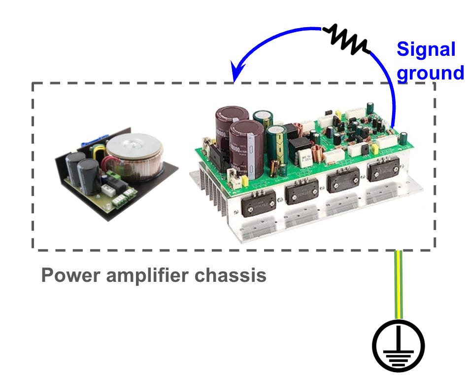
The very dangerous way
One of the easiest ways to avoid a ground loop is by cutting the connection between earth and the chassis of my circuit. This way, the local ground of my circuit would be floating (maybe at a high voltage above earth), with a clean, noise-free signal reference.
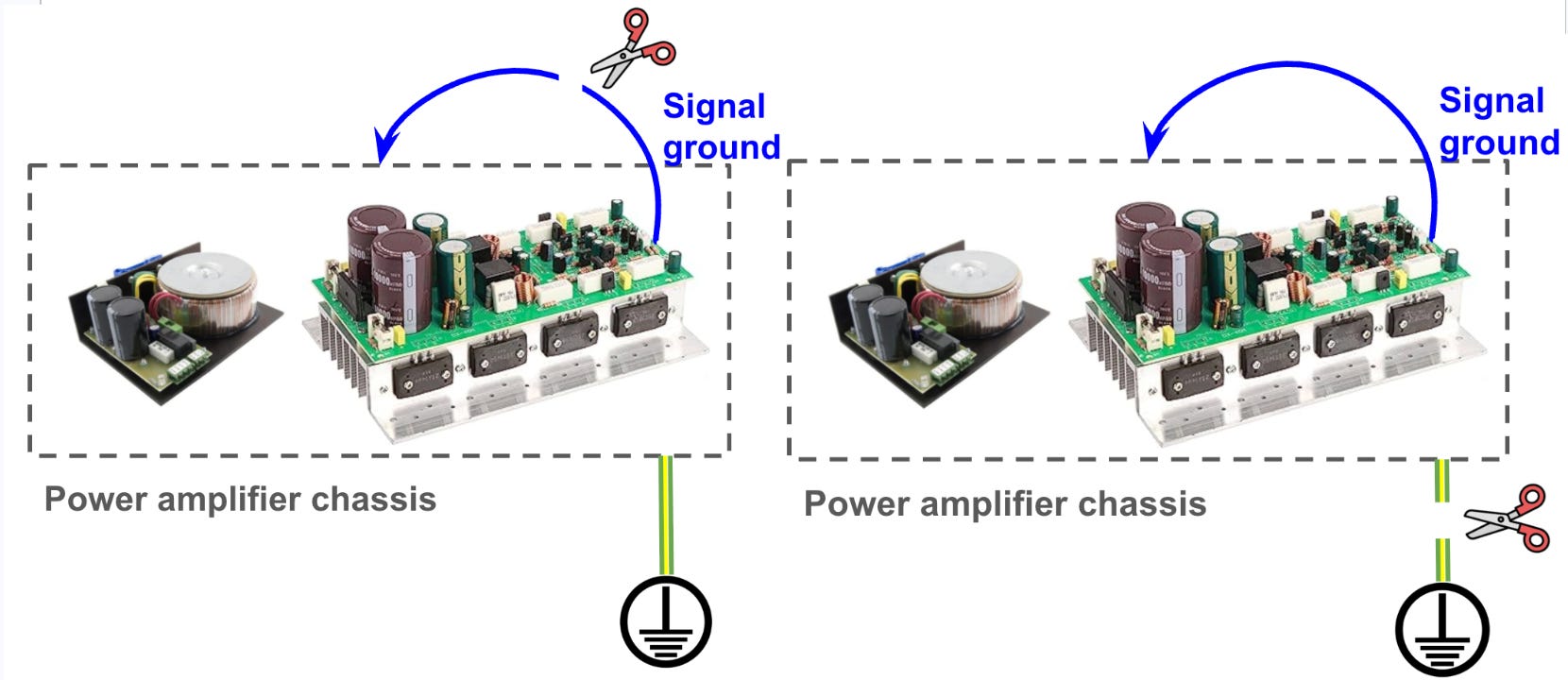
However, this is dangerous and illegal, because now the chassis is not safe: if you have your feet on earth (no flying), and you touch your chassis, the floating voltage of your circuit will pass through your body to earth.
This option, therefore, should be completely discarded.
The dangerous way
Adding a ~10Ω resistor between your common node (signal ground) and earth increases the resistance of the loop significantly, so the total current is reduced, and therefore the noise voltage too. The “hum” is drastically reduced, and your chassis is still connected to earth voltage reference.
However, if a 220V wire touches your chassis by accident, this resistor might burn and create an open circuit, so you would be in the situation of a dangerous floating chassis again. That is why this option should be also discarded.
The not so dangerous way
If we replace the resistor by a “loop breaker” circuit, like this one:
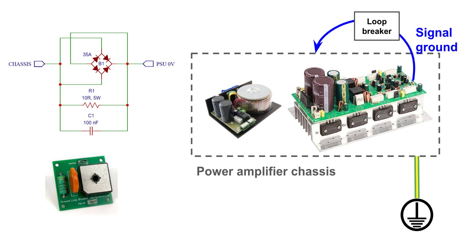
It is a bit safer: in normal circumstances, the diodes do not conduct, and the resistor is limiting the current to earth. In case of accidentally passing 220v through the resistor and burning it, the diodes would suddenly conduct, and the chassis would be safely connected to earth. Note that you should use a high-power, chassis-mounted bridge rectifier (e.g. KBPC3504 rated for 35A and 400V), since in the case of catastrophic short-circuit there can be very high currents involved.
This option, however, is illegal in many countries, because safety regulation indicates that the chassis and earth must be directly connected with a wire, with no intermediate circuitry. The reason is that unlikely malfunction of this circuit could, indeed, leave the chassis floating again, similarly to previous cases.
Some commercially available devices, like Ebtech Hum X implement a similar loop breaker directly on the mains socket. However, there is no agreement about the safety of such devices.

Safe ways
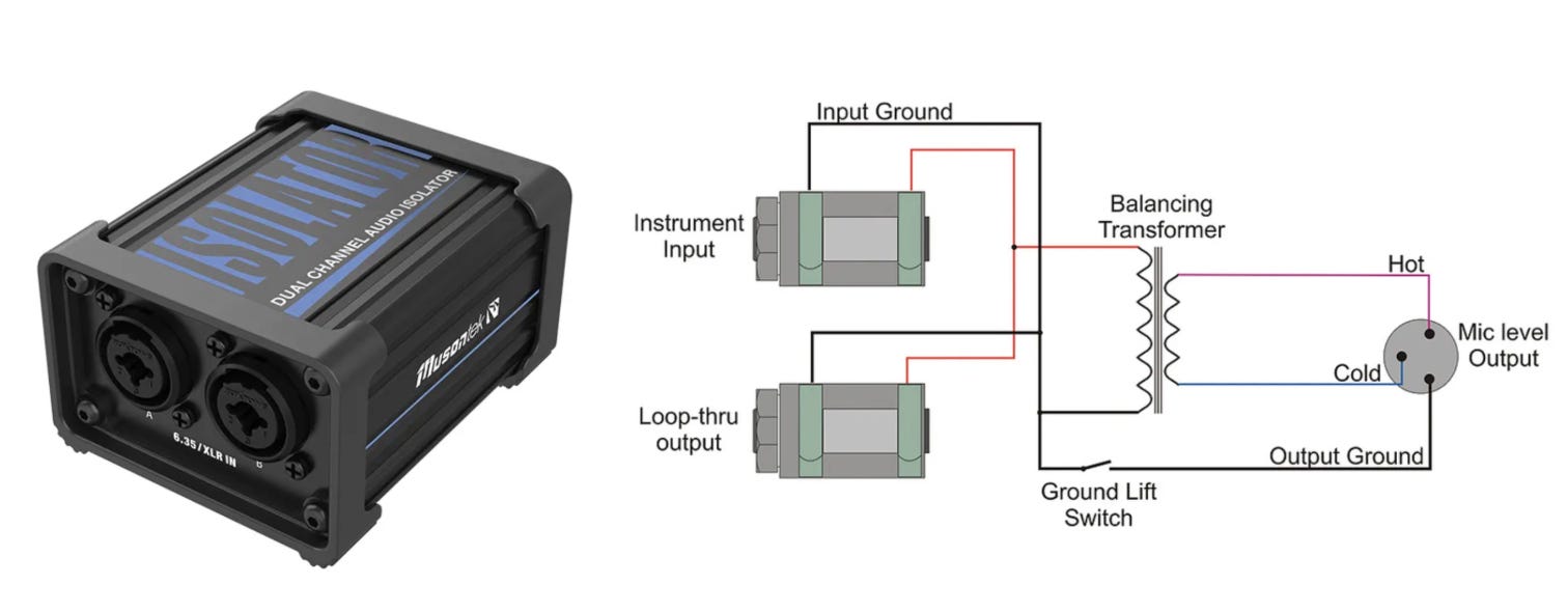
Galvanic or optical coupling
DI boxes and other kind of isolation devices frequently contain a balancing transformer able to isolate completely the input and the output, breaking ground loops. In this way, we can have different voltage levels in the earth at each extreme without interfering with each other.
This is one of the most used ways to avoid ground loops, given that these transformers in professional DI boxes are practically transparent to audio quality. According to Douglas Self, this approach can introduce some LF distortion.
Opto-coupling is also an option to safely separate grounds. Using optical cables (like TOSLINK) or transmitting digitized audio over a network completely breaks the electrical connection between devices, making ground loops physically impossible.
Electronically balanced inputs
This applies either when we use active transformerless DI boxes, or when we work with amplifiers that have fully balanced inputs.
As Cordell and Ott explain, fully balanced amplifier inputs with true differential signals provide the best immunity to interference. Balanced inputs with high common mode rejection at high frequencies are most immune to EMI. In this case the common-mode voltages induce equal currents in both halves of the balanced circuit, and the balanced receiver responds only to the difference between the two inputs. The better the balance, the larger the amount of common-mode rejection. As frequency increases, it becomes more and more difficult to achieve a high degree of balance.

Find the Falstad simulation for this balanced setting here.
Note that shield connection connect the two chassis, not the two signal grounds, according to norm AES48-2005 to avoid the “pin 1 problem”.
Star grounding / Thicker cables connecting chassis or shields
One of the ways to avoid ground loops is using a single socket for all the audio devices, so that we reference all common nodes to the exactly same point of the earth wire. This can be possible in some studio setups, but it is not feasible for large live setups.

Similarly, you can also reduce the impedance of the earth connection between both devices by using an extra thick copper cable between the two chassis to minimize the impedance, or to complement the shield connection: whatever minimizes the impedance of that side of the loop.
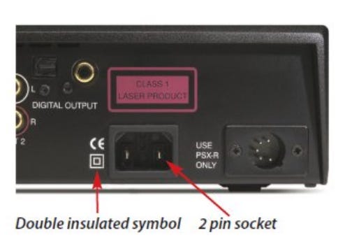
Double-insulated amplifiers
As explained by Douglas Self, mains-powered equipment comes in two types: grounded and double-insulated. These are officially called Class-I and Class-II respectively. Class-II electrical equipment relies on double-insulation and rigorous construction standards rather than a ground connection to ensure safety. While this ungrounded design effectively prevents major ground loops, it sacrifices the ability to use a grounded electrostatic screen, leaving circuitry more vulnerable to mains noise and RF emissions.
Breaking the ground loop in the case of digital noise (e.g. USB)
As mentioned earlier, the ground return path is sometimes contaminated by digital noise rather than 50/60 Hz interference. The remedies parallel the previous cases, with a few nuances:
Star grounding: as before, centralizing plugs and connections into a single star-ground point helps avoid ground loops in studios that mix analog and digital gear.
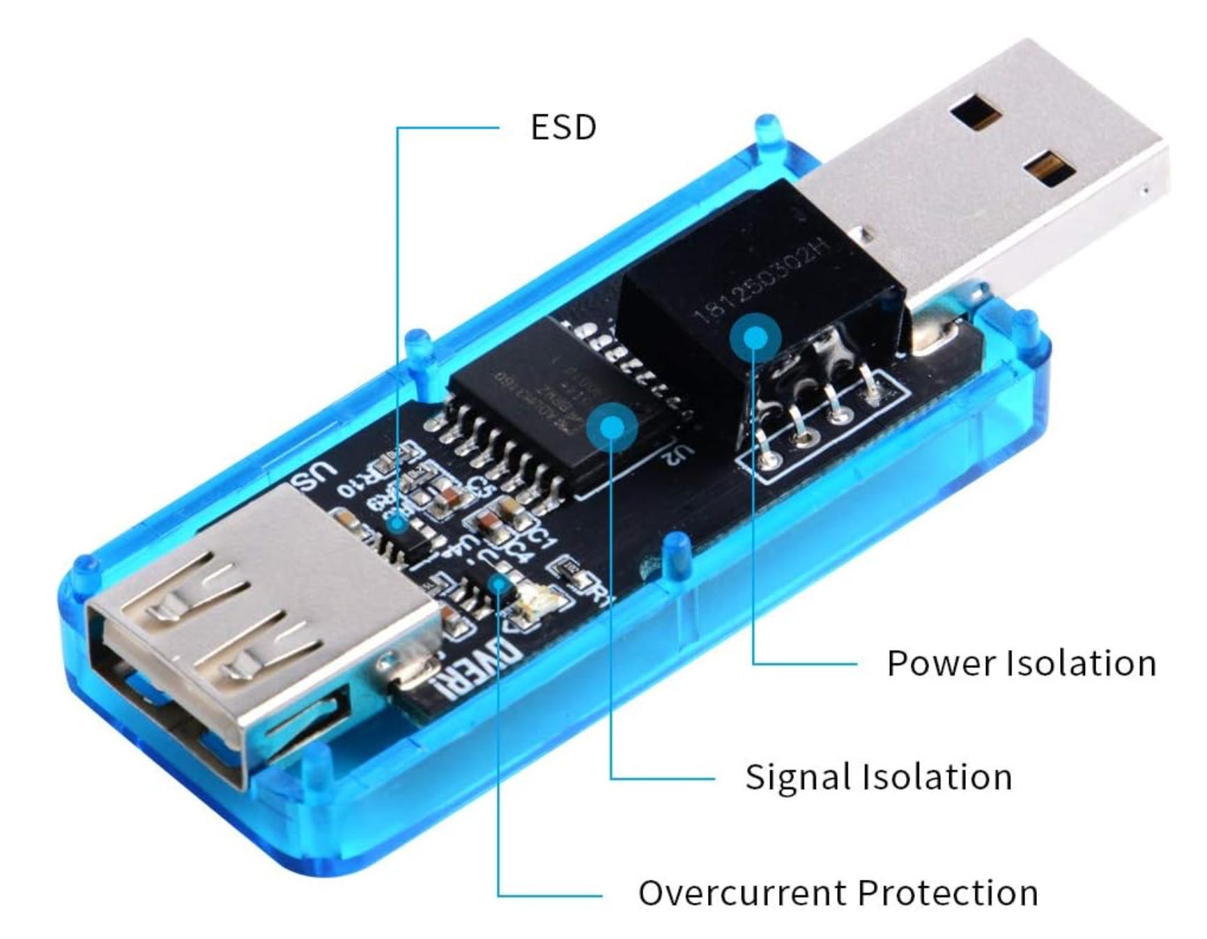
Breaking the loop / galvanic isolation: typically achieved with an external device that isolates both the data lines and the power rail. If the USB peripheral is bus-powered, a separate clean supply is then required on the device side. For MIDI controllers, using a 5-pin DIN MIDI cable instead of USB achieves true galvanic isolation thanks to the optocoupler at the receiver input.
Balanced connections, again are a good way to avoid ground interferences contaminating (either digital noise or hum) your original analog signals.
Avoiding parallel cable runs to minimize capacitive and inductive coupling of the fast-edged digital signals.
The simulation models inserting a USB isolator between a USB audio interface and a PC, galvanically isolating both power and data. The DAC outputs a clean 400 Hz tone. Meanwhile two disturbances inject current into the system: the ~1 kHz current pulses inherent to USB packet traffic, and the ~100 kHz ripple of the PC’s noisy switched-mode power supply. Because the ground return conductor has finite impedance (the 10 mΩ elements in the schematic), these currents develop voltage drops across the shared analog ground (Ohm’s law) and that contaminated reference is exactly what the studio monitor interprets as noise riding on top of the 400 Hz tone. In the schematic, data isolation is represented by a transformer; because the link is isolated, each side must maintain its own local ground reference. Watch how adding a clean supply that is galvanically separated from the PC supply breaks the loop, eliminates the voltage drop across the analog ground, and leaves the tone clean.
How to avoid intra-system ground loops
This section is highly relevant for the practical assembly of audio equipment, particularly for preventing internal ground loops. When components are grounded randomly to the metal chassis, slight voltage differences between these points can cause unwanted currents to flow, resulting in a persistent 50/60Hz background hum. The most effective solution is strategic grounding. By using organized layouts (such as a “star ground” or a dedicated ground bus) you can route all return currents to a single, unified reference point, effectively eliminating the pathways that allow these noisy loops to form.
Separated grounds
According to Coombs, and other references, we should separate the grounds of different nature. Some of the natural groupings might be:
Electrical safety ground
Power supply ground
Low-level analog ground
High-level analog ground
Digital ground
I/O ground
Pulsed power/energy ground
Ground planes
Ground planes can improve the electrical signal integrity of the grounding system. According to Kyttäla, however, ground planes are not easy to handle. The ground plane topology can work amazingly well (properly done it is in some occasions much more effective than using ground buses), however, he does not advise using it unless you are willing to experiment with several different layouts and circuit board prototypes. With ground planes, you have very little control where return currents actually flow and disruptions that break the solidness of the ground plane (there usually will be plenty) cause return currents to flow using very strange paths, which may also turn the PCB into an antenna. Improper use of ground plane arrangement can even contribute to addition of noise, oscillation and hum.
Star-grounding with T-bus in power devices
According to Kyttäla, Douglas Self, and the Hifisonix, the right way to proceed with the grounding of an audio amplifier is not exactly with star grounding. If the interconnection point of the star grounding has a flow of high currents, there might be a slight voltage drop in the various grounds, leading to hum noise. Instead, the star grounding should be done in a small T-shaped bus. One of the branches of the T connects noisy grounds near the diodes bridge, e.g. the capacitors, and there is a high pulsating current passing through it. The other branch of the T acts as a “voltage sensor” somehow, and almost no current flows through it. The different elements in this branch should be connected in a specific order, from cleaner to noisier: (1) preamplifier, (2) small signal amplifier, (3) speaker, (4) digital /protection circuits, (5) chassis, (6) T connection to capacitors.
Kyttäla explains a similar thing, but he merges some of the connections of the T into a “common point”. He suggests the following configurations:
a) Single supply scenario #1 (Transformer has no common connection): Rectifier connects the main filter capacitor(s) and capacitor(s) connect the common point. All other common returns connect only to the common point.
b) Single supply scenario #2 (Center-tapped transformer and two rectifier diodes): Transformer’s common-referenced center tap connects the main filter capacitor(s), which connect the common point. All other common returns connect only to the common point.
c) Dual-supply: Center tap connects the main filter capacitor(s), which connect (recommended) or form the common point. All other common returns connect only to the common point.
Finally, let me show you what Gemini created when I asked it to illustrate the importance of the connections order in the T-bus for proper grounding using the electronic-hydraulic analogy.
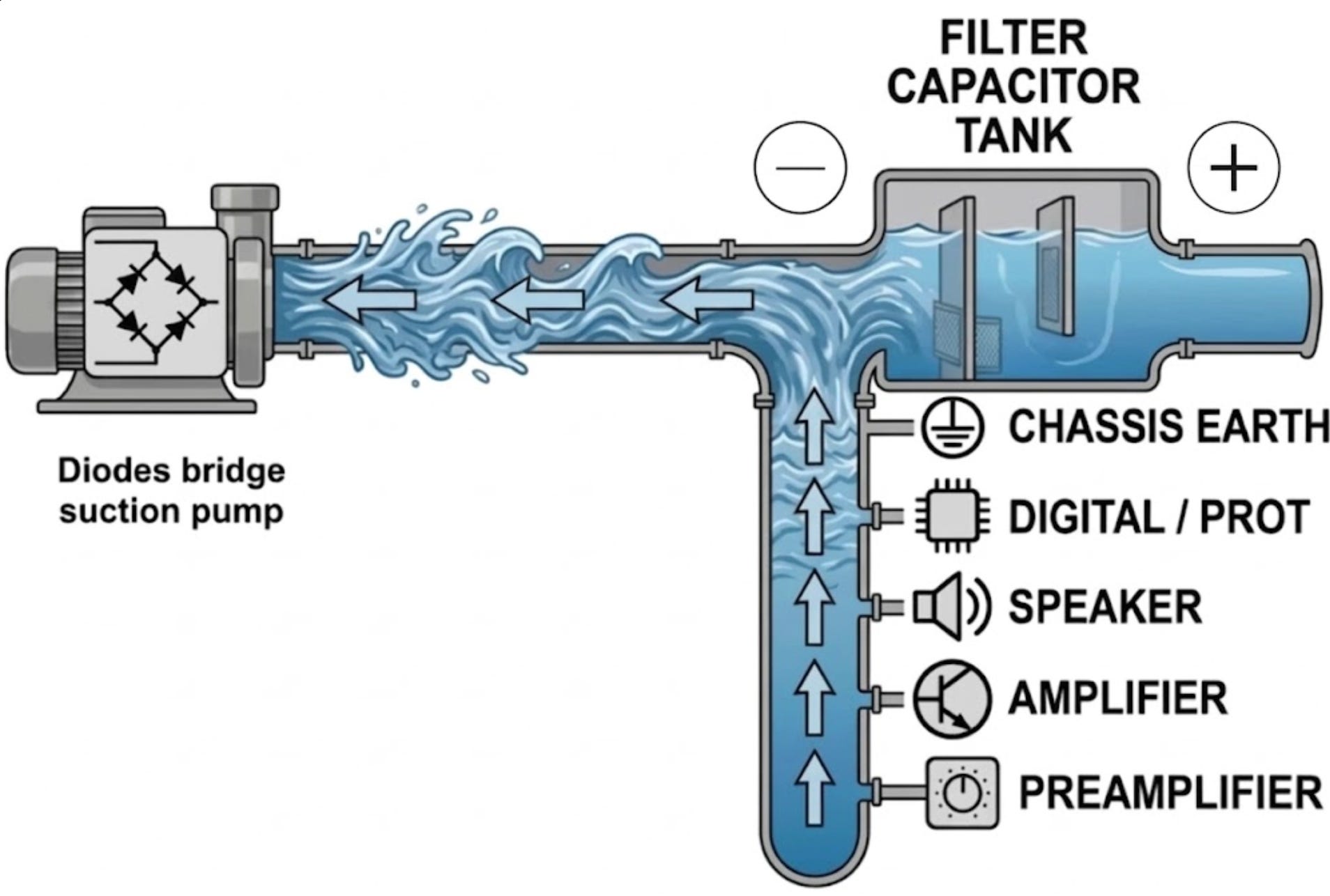
I’m aware the hydraulic analogy can be misleading to explain many electrical phenomena, but I think in this case illustrates well the ideas explained by Hifisonix.
Star grounding vs. RF interference
Star grounding is a good approach for dealing with low-frequency noise caused by ground loops. On its own, however, it does not address RF at the point where the cable enters the chassis. If the shield has no low-impedance path to the chassis there, common-mode RF currents on the shield cannot return to the chassis at the boundary and instead couple into the internal circuit, where they can radiate and produce interference.
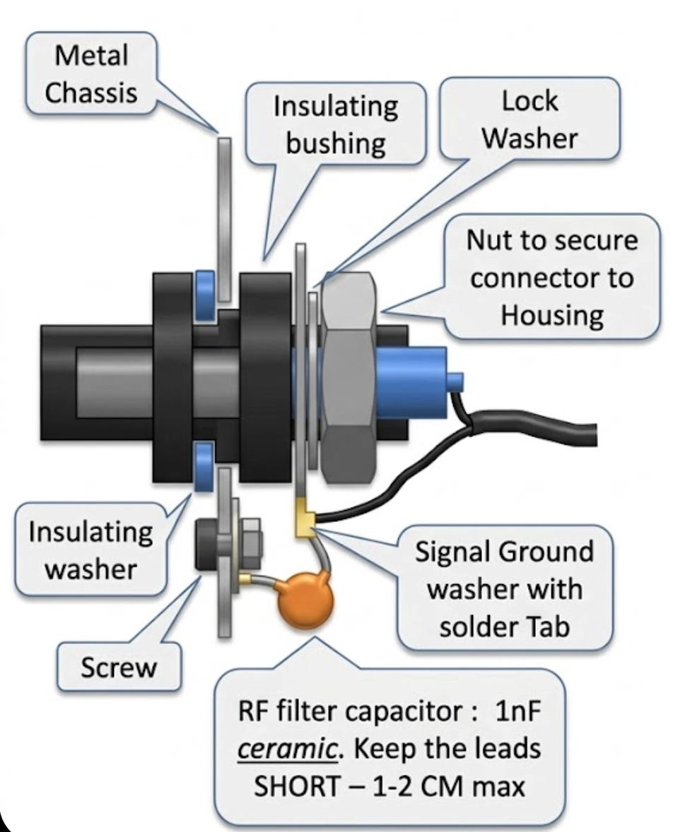
Best practices in electromagnetic compatibility recommend bonding the cable shield to the chassis at the entry point, so that the shield and the chassis form a single continuous enclosure with no gap for RF to penetrate.
These are two independent techniques addressing different problems: star grounding governs how the internal 0V references are tied together, while shield termination governs how the cable shield meets the chassis. A good design applies both. Keep the star grounding to avoid low-frequency ground loops, and separately terminate the shield to the chassis through a capacitor right at the audio connector. The capacitor is an open circuit at low frequencies (no ground loop) and a short circuit at RF (shield bonded to chassis), providing the single-enclosure shielding without reintroducing the low-frequency loop.
Hum noises due to other reasons
Although hum is sometimes caused by ground loops, in many cases it is not. This list describes other mechanisms that can introduce hum or buzz without any ground loop being involved:
Mechanical hum in transformers
The core laminations physically change dimensions as the magnetic flux cycles (magnetostriction), making the transformer buzz audibly. Because the strain depends on flux magnitude regardless of sign, this occurs at twice the mains frequency: 100/120 Hz, not 50/60 Hz. Loose laminations or a hard mounting let the chassis act as a sounding board, and DC on the mains pushes the core toward saturation and makes the buzz much worse. This is primarily acoustic noise radiated into the air rather than noise injected electrically into the signal path, but it can still become electrical hum: the vibration can couple into microphonic components (valves, ceramic capacitors), and a nearby microphone will simply record the buzz from the air. This kind of issue can be reduced by tightening the screws of the transformer, or by re-varnishing in some cases.
Direct inductive coupling of the transformer
The power transformer’s stray magnetic field induces a current directly into nearby signal wiring, input transformers, or the chassis, with no loop or shared conductor required. The effect is strongly geometric: it depends on the distance and the relative orientation between the transformer and the victim wiring. This is why rotating the transformer, or rerouting and twisting signal leads to minimise loop area, can dramatically reduce the hum. It is a near-field, 50/60 Hz mechanism specific to having a mains transformer inside the box.
Capacitive pickup
A changing mains voltage couples through stray capacitance onto any high-impedance node, which then behaves like a small antenna for the 50/60 Hz field. Unshielded signal leads, guitar inputs and tube grids are typical victims, and the human body (itself coupled to the mains) can inject hum the same way. Note this can contaminate either the signal node or the reference node: a floating chassis is just capacitive pickup landing on the reference instead of the signal. The cure is shielding, lowering the node impedance, or firmly defining the reference.
Power supply ripple
After rectification, the reservoir capacitors are recharged in pulses, leaving a residual ripple voltage that leaks into the audio through the circuit’s finite power-supply rejection. Full-wave rectification puts this ripple at 100/120 Hz, so like transformer buzz it sits in the “twice mains” column. A strong 50/60 Hz component instead points to asymmetry: a failed rectifier diode, a half-wave supply, or an unbalanced dual rail. More filtering, better regulation, or higher PSRR stages reduce it.
External mains contamination
Other equipment sharing the AC line injects noise that rides into your supply or radiates into your wiring. Light dimmers are the worst offenders: their triac phase-cutting chops the waveform and produces harsh, harmonic-rich buzz both conducted and radiated. Motors, fluorescent/LED ballasts, fridges and switching supplies add their own contributions. This noise is external to your device, so mains filtering, separate circuits, or distance from the offender are the remedies.
Transducer pickup
Any coil sitting in the ambient mains field will have a 50/60 Hz current induced directly into it, like the secondary of a parasitic transformer. Single-coil guitar pickups are the classic case (this is the hum that humbuckers were designed to cancel) and tape heads and phono cartridges behave the same way. Turntables add a second offender: the synchronous AC motor runs at line frequency and its stray field couples straight into the cartridge and tonearm. None of this involves grounding at all, so the remedies are magnetic: shielding, increasing distance, reorienting the transducer, or using hum-cancelling (dual-coil) designs.
References
Books and technical references
Douglas Self — Audio Power Amplifier Design Handbook, 4th ed.
Bob Cordell — Designing Audio Power Amplifiers
Henry W. Ott — Noise Reduction Techniques in Electronic Systems (1988)
Teemu Kyttälä — Solid State Guitar Amplifiers, v1.0
Clyde F. Coombs (ed.) — Printed Circuits Handbook, 6th ed.
Hifisonix (Andrew C. Russell) — Ground Loops (application note)
Articles and web resources
Sound on Sound — Understanding & Solving Ground Loops
Tomi Engdahl (ePanorama) — Ground loop problems and how to get rid of them
R.G. Keen — Star Grounding in Tube Amplifiers
teemuk (Teemu Kyttälä) — Grounding techniques (ssguitar.com forum)
Standards
AES48-2005 — AES standard on grounding and EMC practices: shields and the “pin 1 problem” (no direct public link; available via the AES standards catalogue).
diyaudio — The pin 1 problem (discussion)
Interactive simulations (Falstad)
Videos
Eric Bogatin — talk on grounding / signal integrity
Discussion thread for this article
Feedback is welcome
I hope this article is useful, and technically sound. I have to admit I’m learning about this topic, so if you think this article should be complemented please let me know. You can find a discussion in the forum diyaudio about this article, with more comments and insights.